
3C Electronic Precision Component Inspection: Division of Labor Between Coordinate Measuring Machines and Vision Systems
Posted2026-9-2
Precision components for 3C electronics typically have tolerances in the micrometer range. When selecting between coordinate measuring machines (CMMs) and vision measurement systems, note that they are not substitutes; each serves distinct roles based on measurement principles, application scenarios, and efficiency. Understanding this division of labor is essential for making the right selection decision.
# 3C Electronic Precision Component Inspection: The Division of Labor Between CMM and Vision Measuring Systems
Precision components in 3C electronics typically feature micron-level dimensional tolerances, strict geometric dimensioning and tolerancing (GD&T) requirements, and complex inspection scenarios. When selecting inspection equipment for these needs, enterprises often face a fundamental decision: should they choose a Coordinate Measuring Machine (CMM) or a Vision Measuring System? These are not mutually exclusive alternatives; rather, they serve distinct roles based on measurement principles, application scenarios, and efficiency positioning. Understanding this division is the prerequisite for making the right selection.
## Measurement Principles Define Application Boundaries
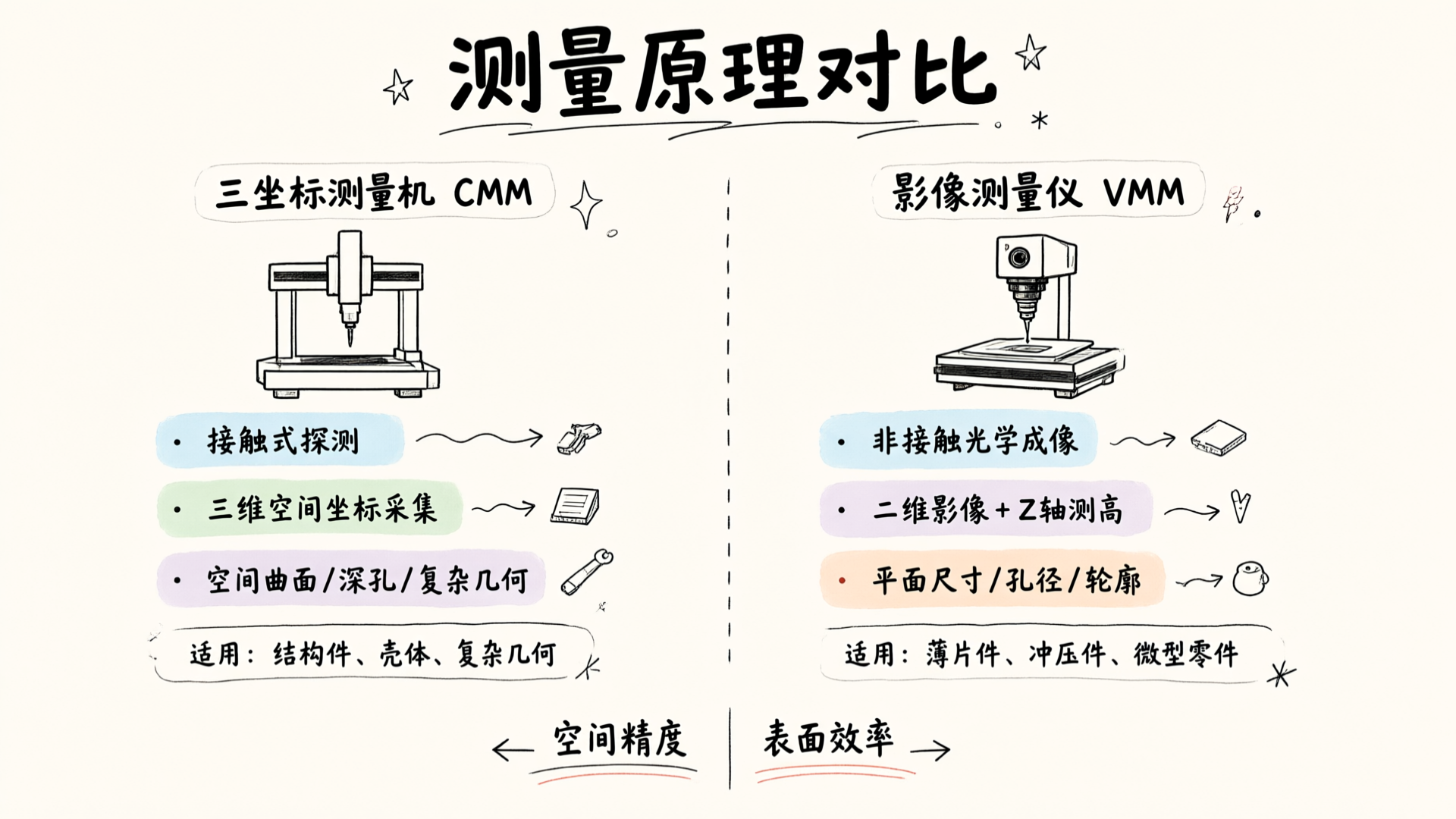
A Coordinate Measuring Machine (CMM) acquires coordinate values at points within 3D space via a probe. Algorithms then fit these points to determine dimensions and GD&T. Its core advantage lies in true 3D spatial measurement—contact probing can effectively handle spatial surfaces, free-form curves, deep hole walls, and composite tolerances of complex geometric elements. For structural features such as internal cavities, coaxiality of stepped holes, and position degrees involving multi-datum systems that require spatial vector calculations, the CMM is irreplaceable.
Vision measuring systems operate on optical imaging principles. High-resolution cameras capture 2D images of workpieces, and algorithms extract geometric features like edges, contours, and hole diameters. Their non-contact nature offers inherent advantages for thin-walled parts, flexible materials, and components prone to surface scratching. While modern vision systems include Z-axis focusing for height measurement to perform limited 3D tasks, their spatial measurement capabilities remain constrained by optical field of view and depth of field.

## Inspection Paths for Typical 3C Components
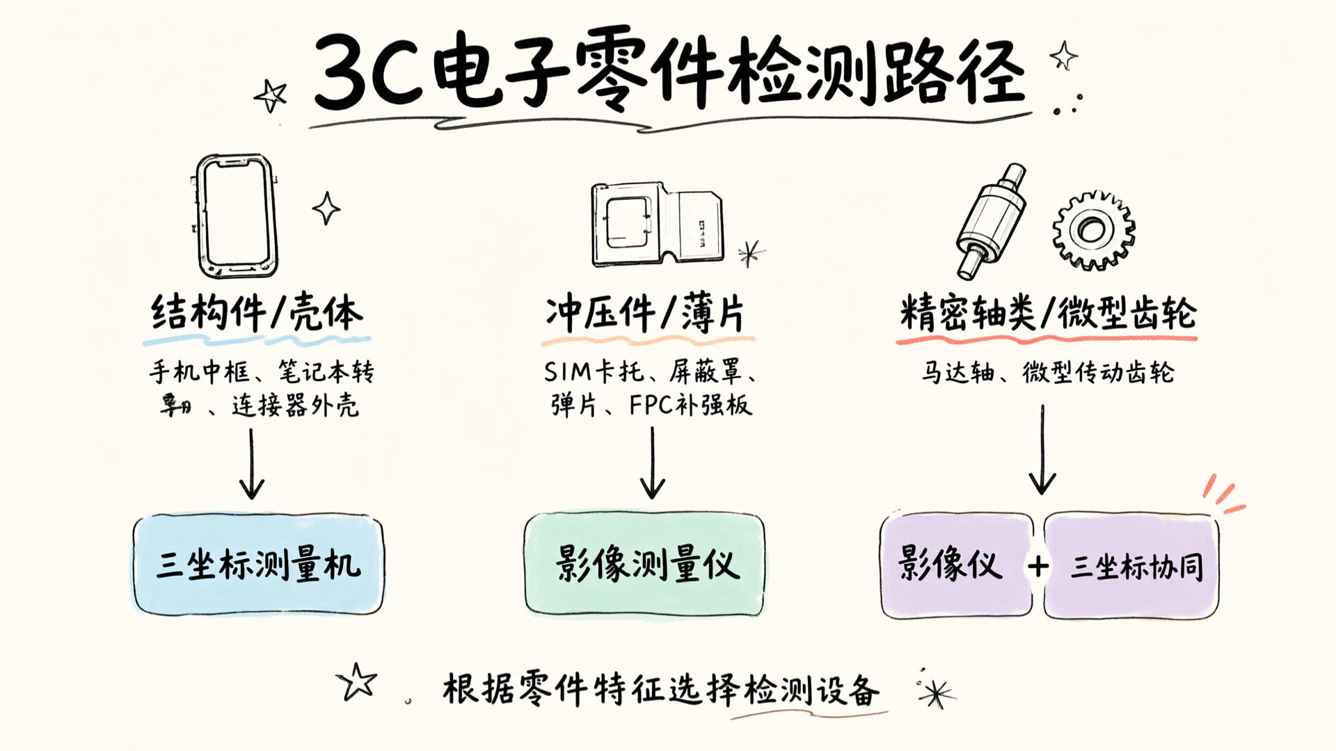
Precision parts in the 3C electronics industry generally fall into three categories, each with distinct inspection paths.
**Category 1: Structural Parts and Housings**
Examples include phone mid-frames, laptop hinges, and connector housings. These parts often feature complex 3D geometries such as stepped holes, snap-fit structures, and curved transitions. Geometric tolerances primarily focus on spatial indicators like flatness, coaxiality, and position. For these applications, the CMM is the standard configuration. Omni series CMMs utilize a moving bridge structure, providing the rigidity, stability, and 3D measurement capability required for such parts.
**Category 2: Stamped Parts and Thin Sheets**
Examples include SIM card trays, shielding cans, spring contacts, and FPC reinforcement plates. These parts are thin and prone to deformation; contact probe force from a CMM may introduce form errors. The non-contact approach of a vision measuring system avoids this issue. Furthermore, in high-volume sampling scenarios, the rapid imaging and batch programming capabilities of vision systems significantly boost inspection efficiency. Versa series vision systems equipped with MicroCore AI intelligent software support AI "fly-shot" technology, enabling multi-feature capture during continuous motion to meet production line cycle time requirements.
**Category 3: Precision Shafts and Micro Gears**
Examples include motor shafts and micro transmission gears within camera modules. These parts are tiny with dense features, demanding extremely high resolution and edge recognition accuracy. High-magnification optical systems paired with sub-pixel edge algorithms give vision systems an advantage here. However, parameters involving 3D gear tooth profile errors or helix deviations still require CMM intervention.
## Four Key Dimensions for Selection Decisions
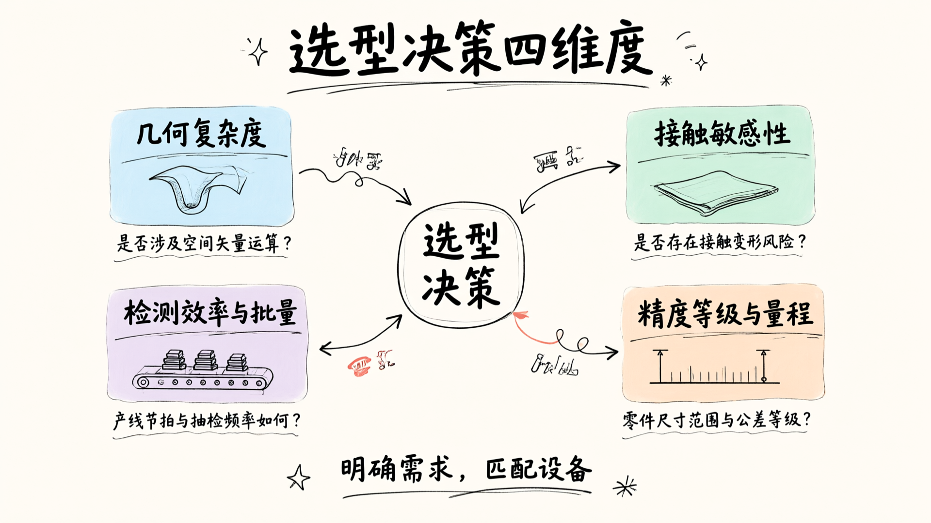
When choosing between these two equipment types, enterprises can establish a decision framework based on the following four dimensions.
**1. Geometric Complexity**
Do the inspection items involve spatial vector calculations? Is measurement of deep hole walls or complex surface profiles required? If yes, a CMM is mandatory. If inspection items are primarily 2D features like planar dimensions, hole diameters, hole spacing, and angles, a vision measuring system is sufficient.
**2. Contact Sensitivity**
Is the part made of soft material, has walls that are too thin, or requires high surface precision that cannot withstand probe contact force? If there is a risk of contact-induced deformation, the non-contact method of a vision system is more appropriate.
**3. Inspection Efficiency and Volume**
What is the required inspection speed for the production line cycle time? What is the sampling frequency? Vision systems typically offer efficiency advantages for rapid inspection of large batches of similar parts, especially when paired with automatic feeders or vibratory bowls. CMMs demonstrate value in full-dimension inspection of single parts with multiple features.
**4. Accuracy Level and Measurement Range**
Each equipment type has its own optimal accuracy range. CMMs maintain spatial accuracy in large travel, high-rigidity scenarios. Vision systems achieve high-resolution measurement in small fields of view with high magnification. Enterprises must match actual part size ranges and tolerance grades against device technical specifications.
## Collaborative Configuration, Not Either/Or
In mature quality assurance systems for 3C electronics manufacturers, both equipment types are typically configured collaboratively. CMMs handle full-dimension first-article inspections, complex part type testing, value transfer, and arbitration measurements. Vision systems handle process sampling, final batch inspection, and rapid sorting. They validate each other within the accuracy system and complement each other in efficiency.
Both Makitec's Omni CMMs and Versa Vision Systems are equipped with MicroCore intelligent measurement software. With consistent data formats, inspection reports, and SPC analysis interfaces, they facilitate the construction of a unified measurement data management system. This software-level unification reduces the risk of data silos during multi-device collaboration.

The core of equipment selection is not determining which device is more advanced, but clarifying your specific component inspection requirements map. By identifying which inspection items must be performed by a CMM and which yield higher efficiency with a vision system, you can plan equipment configurations and budget allocation accordingly to build an economical and reliable quality assurance capability.