
Ensuring Accuracy of Coordinate Measuring Machines: Four Technical Pillars of the Omni Series
Posted2026-9-2
Ensuring Accuracy of Coordinate Measuring Machines: Four Technical Pillars of the CLASSIC Series
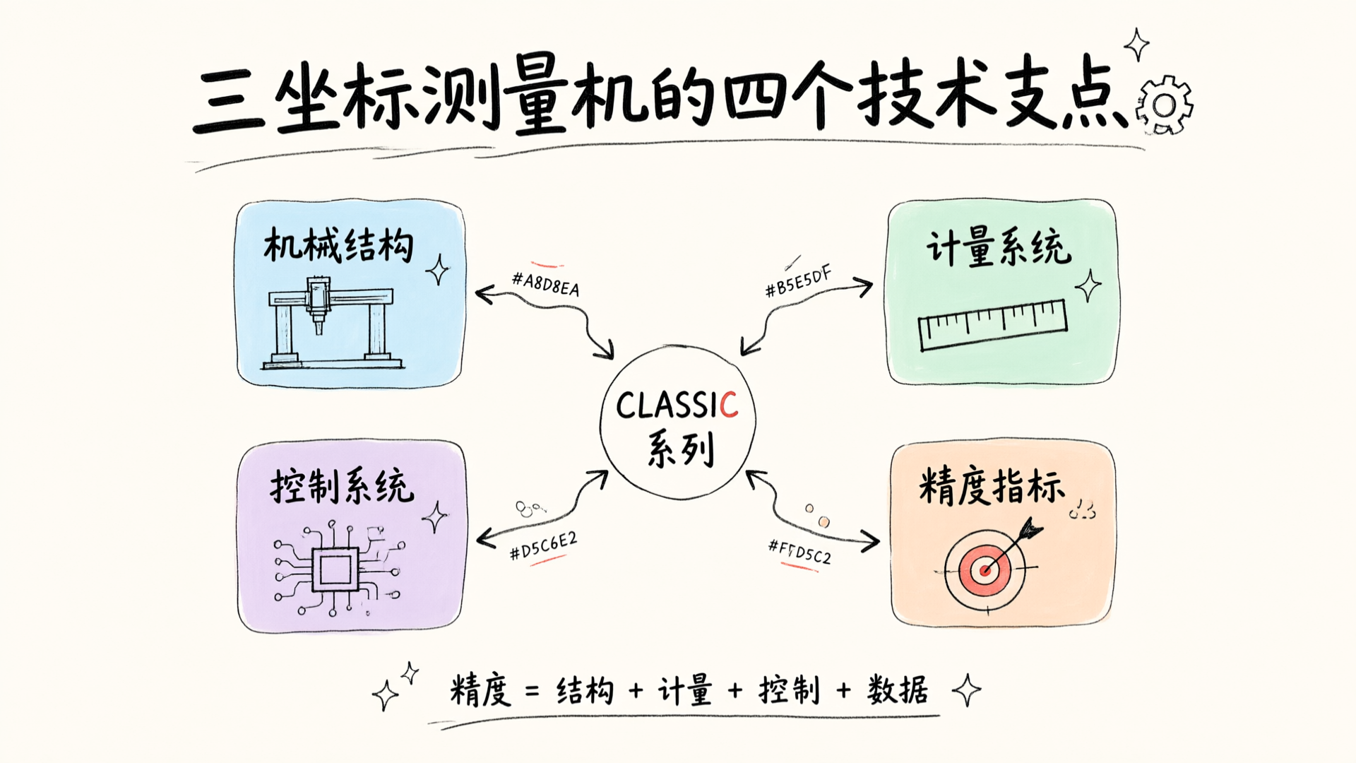
In precision manufacturing, the core value of a coordinate measuring machine (CMM) lies in quantifying geometric deviations to within microns. Whether a CMM can deliver reliable data over the long term depends on the coordinated precision of four key elements: mechanical structure, probe system, control logic, and software algorithms. The design philosophy of the CLASSIC series CMM (JSC686, measurement range 600×800×600 mm) is built around these four dimensions.
Mechanical Structure: Reduces Motion Inertia, Ensures Geometric Stability
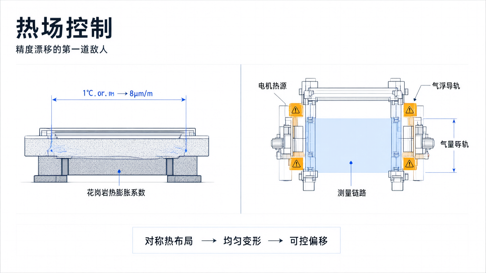
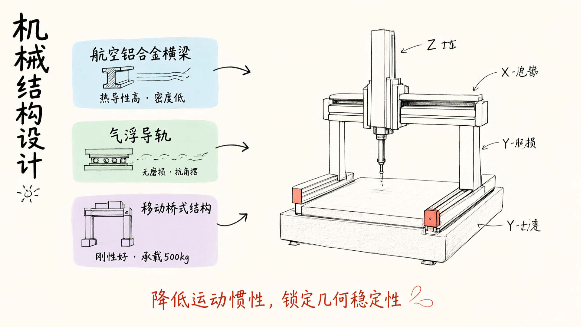
The CMM's mechanical structure is the physical foundation of accuracy. The CLASSIC series features a fully enclosed frame with a moving bridge design. The crossbeam and Z-axis guideways are made from imported aerospace-grade aluminum alloy, with cross-sectional shapes optimized through finite element analysis. This design addresses two key factors: aluminum's higher thermal conductivity than granite allows it to reach thermal equilibrium faster in fluctuating temperature environments, while its lower density compared to steel reduces the mass and inertia of moving components.
The Y-axis guide rail and measurement platform are machined as a single unit with dovetail positioning, ensuring precise geometric alignment between rail straightness and platform flatness. The fixed granite worktable supports loads up to 500 kg, providing a stable reference for clamping large workpieces. The X- and Z-axis aluminum alloy guide rails exhibit superior thermal conductivity, resulting in significantly lower thermal deformation compared to traditional steel rails under varying workshop temperature gradients.
All three axes employ self-cleaning, preloaded high-precision air bearings operating via hydrostatic gas levitation. Compared to rolling guides, air bearings eliminate contact wear and reduce motion resistance; the larger bearing span directly enhances angular stability. The drive system uses DC servo motors with timing belt drives to ensure transmission rigidity while achieving backlash-free motion. The Z-axis features a flexible pneumatic balancer to counteract gravity on the Z-axis assembly and minimize air resonance during low-speed operation.
Metrology System: The Precision Chain of Linear Scales and Probes
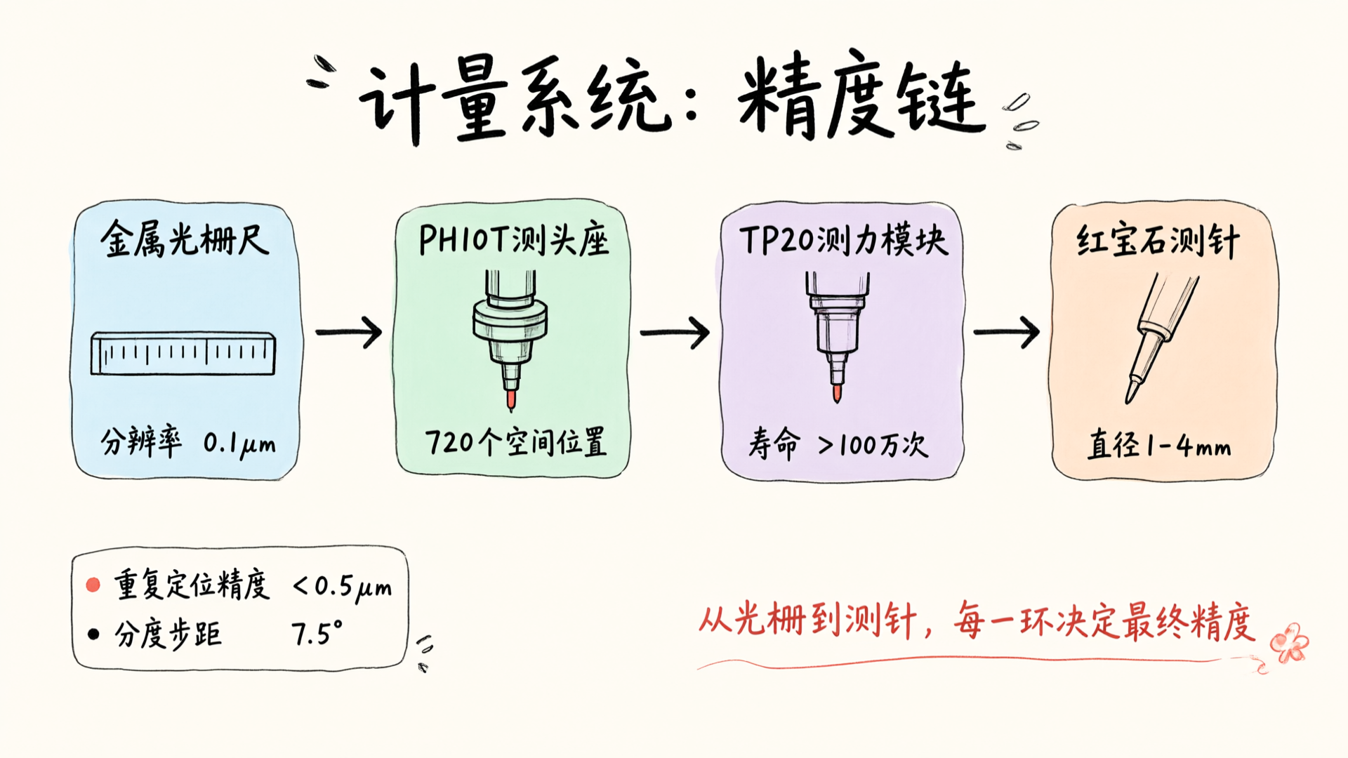
The length measurement system employs a Renishaw reflective metal tape scale with a resolution of 0.1 μm. Since the thermal expansion coefficient of the metal tape closely matches that of the workpiece, the scale and workpiece expand or contract proportionally when temperatures deviate from the standard 20°C environment, partially compensating for systematic errors.
The probe system consists of the PH10T automatic dual-rotation indexing head and the TP20 high-precision force module. The PH10T indexes in 7.5° increments around both the A-axis (0° to 105°) and B-axis (±180°), providing 720 spatial positions with a repeatability accuracy better than 0.5μm. The TP20 force module has a rated lifespan exceeding 100 thousand cycles and senses forces along the ±X, ±Y, and +Z axes. Standard probe sets include ruby ball probes with diameters ranging from 1mm to 4mm and lengths from 10mm to 20mm. These are paired with stainless steel extensions (5mm to 30mm) and aluminum probe extensions (100mm, 200mm) to accommodate various depth and angle measurement requirements.
Control Systems & Software: From Motion Planning to Data Output
The MACC high-speed, high-precision control system features an integrated drive and control design with a built-in DSP motion controller, supporting three-axis closed-loop motion and vector control. Speed planning offers T-curve and S-curve modes, with linear or circular path interpolation available for multi-point continuous motion. The system includes multiple safety modes that trigger millisecond-level shutdown protection during anomalies and provides online fault diagnosis.
The measurement software utilizes XT-DMIS (CAD Advanced Edition) and fully complies with DMIS standards. It supports the measurement and construction of basic geometric elements, including points, lines, planes, circles, cylinders, cones, and spheres. The software calculates form and position tolerances such as straightness, flatness, roundness, cylindricity, parallelism, perpendicularity, coaxiality, and runout. Its self-learning feature allows operators to manually measure a part once to automatically generate a repeatable automated inspection program. The software supports CAD data import (IGES/STEP formats), automatically identifies theoretical features from the model, and drives the coordinate measuring machine for inspection, enabling offline programming and path simulation.
Precision Metrics: Verifiable Performance Data
The performance specifications for the CLASSIC series JSC686 are as follows:
Indication error (MPEE): ≤2.4+3L/1000 mm (L is the measured length, unit: mm)
Measurement Error (MPEP): ≤ 2.2 μm
Ambient temperature requirement: 20±2℃, rate of change ≤1℃/h
Humidity requirement: 40% to 70%
Supply pressure: ≥0.55MPa
Calibration is performed in accordance with ISO10360-2. Five gauge blocks are measured at each of the seven positions within the coordinate measuring machine's working volume, with three repeated measurements per dimension, resulting in a total of 105 measurements. The probe error verification method involves uniformly measuring 25 points on a standard sphere with a diameter of 25 mm; after calculating the least-squares center, the difference between the maximum and minimum radial distances is taken.
Conclusion
The accuracy of a coordinate measuring machine (CMM) is not determined by a single component but is the result of an integrated system comprising mechanical structure, metrology systems, control algorithms, and software compensation. The CLASSIC series is designed with this holistic approach in mind: it uses aerospace-grade aluminum to minimize thermal deformation, employs air bearings to eliminate mechanical wear, incorporates metal scales for temperature deviation compensation, and relies on DMIS-standard software to ensure data traceability. For manufacturing enterprises, selecting measurement equipment should focus not only on factory accuracy specifications but also on whether the underlying technical approach has proven its reliability over long-term operation.